

Cable Size Calculation: Single-Phase and Three-Phase (Calculator)
8/16/2026
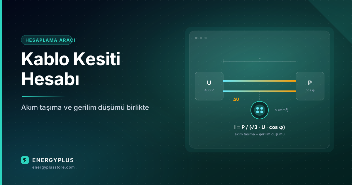
Ampacity and voltage drop criteria, the effect of cos φ, and a calculator that applies both criteria together.
Cable cross-section is not chosen on a single criterion. The correct approach is to apply two criteria separately and take the larger result.
1. Ampacity
The current the cable can carry without overheating. The design current is calculated first:
- Single-phase: I = P / (U · cos φ)
- Three-phase: I = P / (√3 · U · cos φ)
Ambient temperature and grouping corrections are then applied. At 40 °C a PVC cable loses 13% of its capacity; with 4 circuits grouped together it loses 35%. These two factors multiply — ignoring them leaves the cable overheating in service.
2. Voltage drop
ΔU = b · [ρ·(L/S)·cos φ + λ·L·sin φ] · I (b = 2 single-phase, √3 three-phase)
This criterion becomes decisive as the run lengthens. On long runs a cross-section that is adequate for ampacity must often be increased by one or two steps because of voltage drop.
The effect of cos φ
The lower the power factor, the higher the current for the same active power. A load at cos φ = 0.7 draws roughly 36% more current than one at cos φ = 0.95 — cable, breaker and losses all grow accordingly. Power factor correction feeds straight into cable cost here.
Single-phase or three-phase?
For the same power, three-phase current is √3 times lower. At higher powers a three-phase supply means both a thinner cable and less voltage drop.
Calculator
Cable Size Calculator
Single/three-phase — ampacity and voltage drop criteria together
b = 2 (single-phase) or √3 (three-phase). ρ is resistivity at operating temperature (Cu 0.0225 · Al 0.036 Ω·mm²/m), λ ≈ 0.00008 Ω/m unit reactance. S is cross-section (mm²), L is one-way run length.
Circuits = number of loaded circuits grouped along the same route (grouping factor).
- Design current Ib
- 25,5 A
- Correction k
- 1 (1×1)
- Required Iz
- 25,5 A
- Table Iz
- 32 A
- Voltage drop
- 10,64 V
- ΔU ratio
- %2,66
Ampacity requires 4 mm², voltage drop requires 2,5 mm² — the larger was selected.
⚠ Important warnings
- This tool is for PRELIMINARY sizing only; it does not replace project calculations.
- Ampacity values are for IEC 60364-5-52 reference installation method C (30 °C). Values are LOWER for conduit, under insulation or buried installations.
- NOT COVERED: short-circuit withstand (k²S²≥I²t), protective device selection and discrimination, earth fault loop impedance, touch voltage, harmonic loads, parallel cables.
- Aluminium and XLPE values are derived with approximate factors; use manufacturer tables for exact values.
- The installation must comply with the applicable national wiring regulations and standards.
- Responsibility rests with the licensed electrical engineer. EnergyPlus cannot be held liable for the results of this calculation.